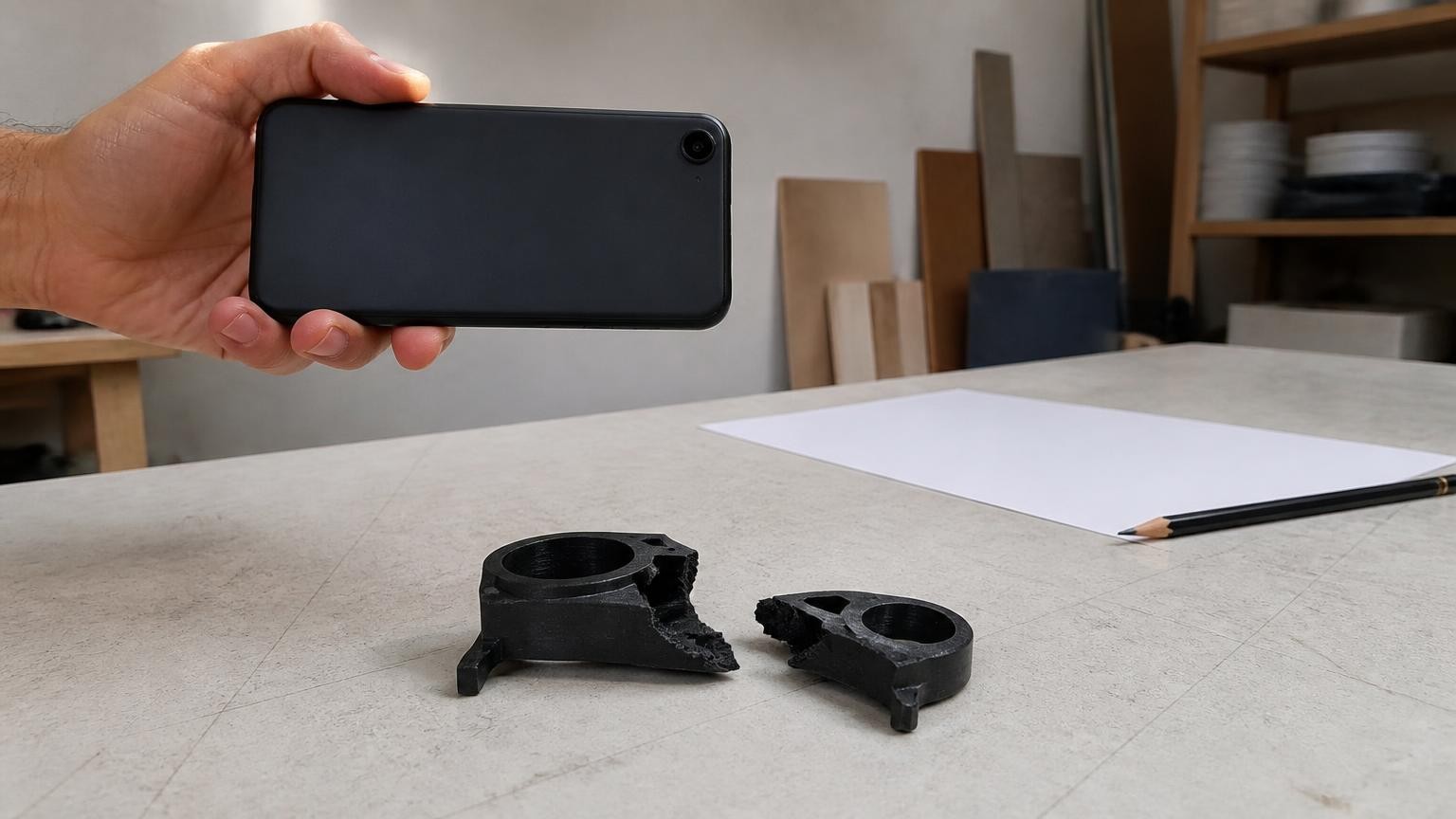
Model the part in CAD when it is made of flat faces, round holes and features that have to fit something else, such as a bracket, an enclosure, a spacer or a clip that snaps onto a rail. Scan it when the shape is curved, irregular or has to follow an existing surface, and rebuild every feature that must fit in CAD on top of the scan.
That split comes from what each method produces. A CAD model stores intent: a 6 mm hole is a 6 mm hole, and you can make it 6.3 mm with one edit. A scan stores a measured surface made of small triangles, with whatever error the scanner added. Many real jobs end up as a mix of both, so the useful question is which parts of the object each method should handle. For a small part there is now also a middle route: a phone app that makes the CAD model from the scan, covered below.
What does a 3D scan actually give you?
An ordinary scan gives you a mesh: a shell of triangles that approximates the surface. The mesh has no idea that one area is a cylinder and another is a flat face, so a bolt hole is just a ring of triangles that happens to be roughly round. To change its diameter you rebuild it; there is no number to edit.
You can turn a mesh into a CAD body, but the result depends on what you feed in. Autodesk's help page on converting a mesh body to a solid body in Fusion says a watertight mesh converts to a solid body, while a mesh with open holes becomes a surface body that you then have to stitch or patch. The same page recommends its Organic method for geometry that came from scan data and its Prismatic method for geometry originally made with solid or surface modelling tools, and it explains that the Faceted method creates one face on the new body for every face of the mesh. Convert a dense scan face by face and you get a heavy body that is still a pile of facets, only now with no dimensions you can edit.
Scans also arrive with defects that a slicer does not forgive. The Blender 3D Print Toolbox manual explains that every edge of a printable mesh should connect exactly two faces, and an edge attached to only one face means there is a hole in the mesh. It also warns that faces forming very thin geometry might be missed entirely by the slicer. The holes usually sit where the camera never looked: the underside, the inside of a deep pocket, the back of a clip. Our guide on how to fix holes and clean up a 3D scan walks through the repair.
How accurate is a phone scan compared with what a print needs?
Published tests give a realistic range. A study of the iPhone 12 Pro LiDAR, published in Scientific Reports in December 2021, reports that objects with a side length above 10 cm were modelled with an absolute accuracy of ±1 cm. A 2026 paper in Geodetski vestnik, which tested the LiDAR in the iPhone 12 Pro, 13 Pro Max and 15 Pro Max with the Scaniverse app, found errors of less than 1% of the object's dimensions for small and medium objects, and significant local deviations on large homogeneous surfaces.
Now compare that with the printer. Prusa's guide to modelling with 3D printing in mind says an Original Prusa is accurate to at least 0.2 mm, that two parts modelled with zero-tolerance dimensions will probably not slot together, and that a good starting gap for movable parts is at least 0.3 mm.
Put those numbers side by side and the problem is plain. Even at the 1% figure, a 50 mm part can be off by 0.5 mm, more than the 0.3 mm starting gap Prusa suggests for a moving fit. A scanned shape is fine where half a millimetre does not matter, such as the outside of a handle. It is not fine for a bearing seat, a snap fit or a hole a shaft has to slide through. Those features need a caliper measurement and a CAD dimension.
Two caveats. These tests measured iPhone LiDAR; photogrammetry and dedicated scanners behave differently, and your own lighting and technique change the result too, so test your setup on a part you can measure. And scale errors are separate from shape errors: if the overall scale is off, every dimension is off. Check the scan against one measured length, as described in how to scale a 3D scan to real-world size.
When should you model the part from scratch in CAD?
Go straight to CAD when most of the part can be described with a ruler and calipers:
- Prismatic parts. Brackets, spacers, mounting plates, enclosures and adapters are flat faces, straight edges and holes. A mesh scan rounds off sharp edges and adds ripple to flat faces, so you end up redrawing them anyway.
- Anything that mates with another part. Shaft holes, threads, press fits, clips and slides need the clearance you choose, not the one the scanner happens to give you.
- Small features. Threads, thin ribs and small holes sit close to the error of a phone scan, so they come out blurred, rounded or closed.
- Parts you expect to change. If version two has to be 5 mm longer or needs a second screw hole, a parametric model takes one edit. A mesh takes rework.
- Parts that must print well. In CAD you set wall thickness on purpose. Prusa's guide notes that walls thinner than one nozzle perimeter are not printable, and a scan of a thin plastic part can easily produce walls like that.
A good test: if you can sketch the part on paper with every dimension written on it in a few minutes, CAD will be more accurate than a scan and often just as quick.
When is scanning the better choice?
Scan when the shape itself is the hard part:
- Organic and freeform shapes. Grips, handles, figurines, sculpted trim and anything with compound curves are slow to model by hand and quick to capture.
- Parts that must follow an existing surface. A mount that sits on a curved dashboard, a cover for an odd-shaped device or a cradle that holds a specific object all need the real geometry of the thing they touch. Scan that surface, then model the part against it.
- Broken or discontinued parts without drawings. Even when you will remodel the part in CAD, the scan records curves you cannot measure with calipers and keeps the overall proportions right.
- Replicas where appearance matters more than fit. Props, display pieces and decorative copies can often be printed straight from a cleaned, watertight scan.
For this kind of capture a phone is often enough. MagiScan turns an iPhone or Android phone into a 3D scanner and measuring tool and exports scans for 3D printing. If you are unsure whether your object needs more than a phone, read do I need a 3D scanner or is a phone app enough.
How do you combine a scan with CAD?
The hybrid route suits any part that has both a freeform shape and features that must fit. The scan supplies the shape; CAD supplies everything that has to be exact.
- Scan and check the scale. Capture the part, then compare one measured length on the scan with the real object. Fix the scale before you trust anything else.
- Clean the mesh. Close the holes, delete the table surface and stray fragments, and make the mesh watertight so it converts and slices cleanly.
- Export a mesh your CAD tool reads. STL and OBJ are the usual choices; how to export a 3D scan to STL, OBJ or USDZ explains the differences.
- Import it as a reference, not as the part. Place the mesh in your CAD tool, cut sections through it and sketch over those sections. Model flat faces, holes and fits as real features, with dimensions taken from calipers.
- Convert only the organic areas. Where a freeform surface has to stay as scanned, convert that region with an organic conversion method and combine it with the modelled features.
- Add clearances and print a test piece. Apply the gap your printer and material need, then print only the critical feature, such as the hole or the clip, before you print the whole part.
The order matters. Starting from the scan and placing exact features into it keeps the modelled holes and faces lined up with the real shape, instead of guessing where a curve should meet them.
Can a phone app make the CAD model for you?
For a small part, it can try. MagiScan 2.0 has a print-ready mode: scan a part such as a clip, a knob or a bracket, and you get a CAD model with dimensions and an STL file for your slicer. The aim is flat faces and round holes instead of a melted mesh, which is where an ordinary scan is weakest.
Check these limits before you rely on it:
- Real size needs a reference. The mode does not use LiDAR, so put a reference object of known size in the frame. Without one, treat the dimensions as an estimate. The LiDAR tests above say nothing about this mode.
- It is labelled experimental. The App Store notes for version 2.0 call the new mode experimental and list "Create a parametric 3D model" among its uses. Neither those notes nor the site gives an accuracy figure.
- Editing is unconfirmed. Neither page says whether the model opens and edits in your own CAD program, so test that first.
- Check your platform. As of 5 November 2026 the Google Play listing does not mention the mode, so on Android check that your version has it.
Treat the result like a first draft of your own: read the key dimensions against calipers and print the critical feature as a test piece. If a shaft hole or a snap fit comes out wrong, model that feature in CAD.
What mistakes cost the most time?
- Printing a raw scan of a mechanical part. It looks right and does not fit, because the fit was measured with scanner error rather than designed.
- Trusting scan dimensions over calipers. Use the scan for shape and position, and calipers for anything that has a tolerance.
- Converting the whole dense mesh face by face. The result is slow to work with and still not editable by dimension. Simplify the mesh or convert only the region you need.
- Modelling exact sizes for parts that fit together. Design the gap in from the start rather than sanding parts after printing.
- Skipping the mesh checks. Holes and very thin areas cause slicer errors or missing walls; check the mesh before slicing, not after a failed print.
So which should you choose?
| Question about your part | Better starting point |
|---|---|
| Mostly flat faces, holes and straight edges? | CAD from scratch |
| Has to fit another part, a shaft or a screw? | CAD, or CAD features placed on a scan |
| Curved, sculpted or shaped around something else? | Scan, then model against it |
| Broken part with curves and no drawing? | Scan as a reference, then rebuild in CAD |
| Small, simple part you would rather not model? | Try a print-ready scan, then check it with calipers |
| Decorative copy where fit does not matter? | Scan, clean and print |
CAD wins for anything that has to fit, scanning wins for anything that has to match a shape, and a part that has to do both is best built from a scan plus CAD features. If your part starts with capturing a shape, MagiScan covers that step on a phone: for a small part, try its print-ready mode and check the result with calipers; otherwise clean and scale the mesh, and the CAD work begins from there.
Frequently Asked Questions
Can I 3D print a scan directly without using CAD?
Yes, if the mesh is watertight and the part does not have to fit anything. Decorative copies and organic shapes often print well from a cleaned scan. For parts with holes, clips or mating faces, rebuild those features in CAD first, or try a print-ready mode and check it with calipers.
Can I turn an STL scan into an editable CAD model?
Partly. Fusion converts a watertight mesh into a solid body and an open mesh into a surface body, but the result follows the scanned faces and has no feature history. For a model you can edit by dimension, use the scan as a reference and remodel the key features.
How accurate does a scan need to be for a replacement part?
It depends on the feature. Outer shapes can often tolerate some error, but fits cannot: Prusa suggests starting with a gap of at least 0.3 mm for movable parts, which is smaller than the error a phone scan can carry on a mid-sized part. Measure those features with calipers and model them.
Is a phone scan good enough for 3D printing a part?
For capturing shape, often yes: the 2026 Geodetski vestnik study cited above reports iPhone LiDAR errors of less than 1% of the object's dimensions for small and medium objects. That is good enough for organic surfaces and for a modelling reference, but too coarse to print precise fits straight from the scan.